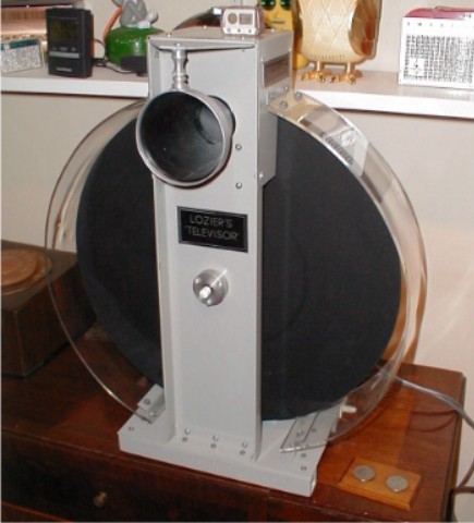
The receiver is built in the same fashion. Notice that since this equipment is used n public demonstrations I thought it necessary to make clear plastic guards. I cut wood forms to the correct diameter and then laid the plastic sheet on top inside of the kitchen electric range. I then slowly increased the temp until the plastic sagged into place... It worked! and the oven stink was gone after I ran it through its high temp cleaning cycle. I guess it is a good thing I am a batchelor.....
Way back then the light source for the scanner was a neon gas discharge lamp.... The problem with these lamps was the fact that the lifetime was limited to only a very few hundred hours at best. These now rare lamps would never stand the rigors of day long demonstrations.
Fortunately there are now light emitting diodes (LED's) that duplicate the pink/orange of neon almost exactly.
The light source consists of 19 LED's of the T- 1 3/4 (5mm) form factor with a 20 degree beam pattern. In order to make the cluster appear as an even illumination, I had to place a diffuser about 3/8 " above the lamps. I tried frosted polyester sheet for the job but decided that the light loss was just too much. I began to think about how other designers diffuse light without introducing much loss...The first thing I thought about was how do light bulb manufacturers diffuse the light of a tungsten filament? One old way was to etch the inside of the glass bulb with acid but modern bulbs made in the US or China no longer do this.... However, I found that Tungsram in Hungary and other former Eastern Block countries still make some ordinary bulbs this way. So I bought a pack of 75 watt Hungarian bulbs at the Dollar Store and headed for my workshop...
I found that it was fairly easy to break open a bulb and then chip it down to a shard about 2" in diameter. I then chucked a wood disk in my lathe and cut a depression to accept the shard. Then I used a liberal amount of hot melt glue to bond the shard to the depression. Then I could use my Dremel Moto Tool with a 1" diameter cut-off wheel to cut a perfect groove in the glass as the lathe rotated at slow speed. All I had to do was make sure that the glass did not heat up, I took the precaution of misting the cut with water as I worked.... In a few minutes I had a perfect diffuser disk which easily released from the glue with the aid of gentle heating from a heat lamp. The excess glue peeled of with no trouble at all... Ta-Dah!
So here at left is my current setup for televising my Felix. He stands on an old aluminum foil Christmas tree rotator from the 1960's. Illumination is from two 150 Watt - 130 Volt (long life) reflector flood lamps. (These lamps are running at somewhat lower voltage and therefore not as bright but it also means that they are producing much less light modulation due to the 60 Hz. power.) I placed a piece of transparent orange lithographers masking film over the photo cell in my camera to make my camera virtually blind to flourescent and arc discharge lighting that may be in the room.
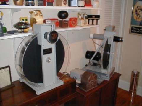
Here are the receiver on the left and the camera on the right. In between is a little gray box that contains the power supply and amplifier to drive the LED light source of the receiver. I can separate the two units with about 50 feet of 75 Ohm coax if necessary.
Since both motors are sychronous, they will run all day long in synch.. Getting the disks to sync manually is a bit of a chore... It can take anywhere from 20 seconds to two minutes to find the right spot.